

Menu
acousticbar.application
Acoustic Detection Systems
ProductSettings Description
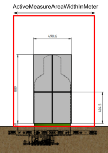
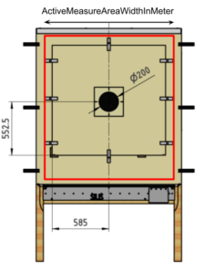
ActiveMeasureAreaWidthInMeter
Width of the measuring area in which shots are calculated [m]
The active measuring area is the range in which the detection system should calculate and send shots to the AthleteMonitor.
The active measuring range is a rectangle, the width of which is defined with this parameter.
In the pictures below, the red rectangles are examples for active measurement areas of an open and a closed detection system:
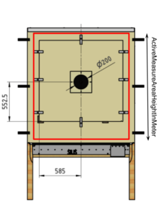
ActiveMeasureAreaHeightInMeter
Height of the measuring area in which shots are calculated [m]
The active measuring area is the range in which the detection system should calculate and send shots to the AthleteMonitor.
The active measuring range is a rectangle, the height of which is defined with this parameter.
In the pictures below, the red rectangles are examples for active measurement areas of an open and a closed detection system:

CalibrationOffsetXInM
Device-specific X-coordinate calibration value [m]
Under construction
Device-specific horizontal correction value of calculated coordinates in meters. This setting is intended to correct target inaccuracies e.g. from inexactly mounted target pictures. This value is usually determined by measuring the deviation of multiple calibration shots.
Remark: The correction is always horizontal and a positive value is a correction to the right, independent of other settings like MountingFlipXZ or MountingRotZInDegree.
Example: value = 0.01
A shot with coordinates (X: 0.045 m / Y: -0.2 m) will be corrected and counted as (X: 0.055 m / Y: -0.2 m).
This value should be used when the target picture is mounted 1 cm right of the nominal position.
Default value: 0
CalibrationOffsetYInM
Device-specific Y-coordinate calibration value [m]
Under construction
Device-specific vertical correction value of calculated coordinates in meters. This setting is intended to correct target inaccuracies e.g. from inexactly mounted target pictures. This value is usually determined by measuring the deviation of multiple calibration shots.
Remark: The correction is always horizontal and a positive value is a correction to the right, independent of other settings like MountingFlipXZ or MountingRotZInDegree.
Example: value = 0.01
A shot with coordinates (X: 0.045 m / Y: -0.2 m) will be corrected and counted as (X: 0.045 m / Y: -0.19 m).
This value should be used when the target picture is mounted 1 cm above the nominal position.
Default value: 0
InternalRefTranslatXInM
Device internal X-offset [m]
Under construction
Warning: This setting must not be changed by customers. It is intended for OEM system manufacturers only.
Specifies the X distance from the detection systems reference point to the measurement systems reference point (in the detection system’s coordinate system orientation)
Default value: 0
InternalRefTranslatYInM
Device internal Y-offset [m]
Warning: This setting must not be changed by customers. It is intended for OEM system manufacturers only.
Specifies the Y distance from the detection systems reference point to the measurement systems reference point (in the detection system’s coordinate system orientation)
![]()
| Device | Default Value [m] |
| ACB01 | 0.896 |
| ACB02 | 0.596 |
| ACB03 | 0.9 |
| ACE01 | 0.053 |
| ACF01 | 0 |
InternalRefTranslatZInM
Device internal Z-offset [m]
Under construction
Warning: This setting must not be changed by customers. It is intended for OEM system manufacturers only.
Specifies the Z distance from the detection systems reference point to the measurement systems reference point (in the detection system’s coordinate system orientation)
| Device | Default Value [m] |
| ACB01 | Not supported |
| ACB02 | Not supported |
| ACB03 | Not supported |
| ACE01 | 0.0854 |
| ACF01 | Not supported |
MaxCadence
Sets the device into maximum cadence mode to support higher rates of fire
When activating this mode, the use of Shotsensors for crossfire detection is no longer supported!
During normal operation, the coordinates are calculated after the shot, which takes a maximum of 50 ms. Therefore, the system cannot detect faster than 1200 shots per minute. (For some products the maximum rate of fire is even lower, due to other reasons – see table below)
In “MaxCadence” mode, raw data is stored in a buffer for max. 40 shots. As soon as no shot is registered for 0.5 seconds, the shots are calculated and the system is inactive for several seconds.
See the table below for maximum accessible rates of fire.
| Device | Maximum Rate of Fire (Normal Mode) | Maximum Rate of Fire (MaxCadence Mode) |
| ACB01 | 1200 RPM (50ms) | 1875 RPM (32ms) |
| ACB02 | 1200 RPM (50ms) | 1875 RPM (32ms) |
| ACB03 | 1200 RPM (50ms) | 1875 RPM (32ms) |
| ACE01 | 1200 RPM (50ms) | 2400 RPM (25ms) |
| ACF01 | 180 RPM (333ms) | 1875 RPM (32ms) |
| S101G3 | 180 RPM (333ms) | 1875 RPM (32ms) |
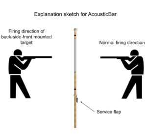
MountingFlipXZ
Specifies whether the target is mounted back-side-front
Not supported for AcousticEye
This setting must be set when the target is mounted back-side-front (e.g. behind the wall). In this case the X-coordinates must be mirrored around the measurement system’s reference point (e.g. center for AousticBar)
Example: value = 1
A shot’s coordinates (X: 0.045 m / Y: -0.2 m) will be corrected to (X: 0.055 m / Y: +0.2 m) because the bullet hits the measurement system from its back side.
| Device | Default Value |
| ACB01 | 0 |
| ACB02 | 0 |
| ACB03 | 0 |
| ACE01 | Not supported |
| ACF01 | 0 |
MountingRefKind
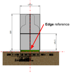
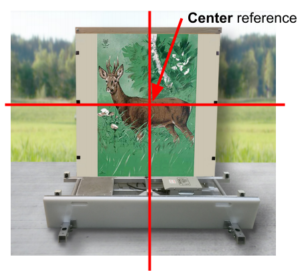
Specifies the targets used reference point for mounting target pictures
Depending on which kind of target picture has to be mounted on the measurement system, this setting has to be set accordingly:
To mount a target picture with a center reference, the measurement system must be set to MountingRefKind = CenterReference.
To mount a target picture with an edge reference, the measurement system must be set to MountingRefKind = EdgeReference
| Device | Default Value |
| ACB01 | Center Reference |
| ACB02 | Center Reference |
| ACB03 | Center Reference |
| ACE01 | Edge Reference |
| ACF01 | Center Reference |
| S101G3 | Center Reference |
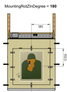
MountingRotZInDegree
Reflects the mounting type of the target (e.g. roof) as an angel [°]
In the event that the measuring system is mounted rotated (e.g. wall or roof), the mounting angle (in degree) must be applied to this setting to ensure that the coordinates are calculated correctly.
Examples:
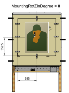
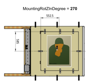
Default: 0
OverrideMicAmplification
Override the used microphone amplification
If a value other than “Inactive” is selected, the microphone gain is set to the corresponding value.
Default is Inactive
SaTriggeredInternally
Trigger SignalAnalyzer internally instead of from TimeDifferenceRecorder (SaChannelThreshold)
Default: false
SaChannelThreshold
Threshold when SignalAnalyzer internally triggered (50 ≙ 1V)
Setting only applies when SaTriggeredInternally set true, otherwise SignalAnalyzer is always triggered from TimeDifferenceRecorder.
SaConversionSpeed
SignalAnalyzer’s conversion speed divider value for calculating sampling frequency
The set value is a register value, which is a divider that can be used to derive the sampling frequency from the clock frequency.
Default value: 8 (≙500 kS/s @ 50 MHz clock frequency)
SaPreMeasurements
Number of recorded measurements before trigger by SignalAnalyzer
| Device | Default Value |
| ACB01 | 32 |
| ACB02 | 32 |
| ACB03 | 32 |
| ACE01 | 32 |
| ACF01 | 128 |
| S101G3 | 128 |
SaMeasurements
Total number of recorded measurements by SignalAnalyzer (including SaPreMeasurements)
When MaxCadence mode is active, the maximum supported value is 64.
| Device | Default Value |
| ACB01 | 64 |
| ACB02 | 64 |
| ACB03 | 64 |
| ACE01 | 64 |
| ACF01 | 256 |
| S101G3 | 256 |
TdrCounterOverflow
TimeDifferenceRecorder’s overflow value for channels which do not trigger
| Device | Default Value |
| ACB01 | 650000 (≈ 2.23m) |
| ACB02 | 650000 (≈ 2.23m) |
| ACB03 | 650000 (≈ 2.23m) |
| ACE01 | 650000 (≈ 2.23m) |
| ACF01 | 650000 (≈ 2.23m) |
| S101G3 | 650000 (≈ 2.23m) |
OverrideMicTrigger
Override the used microphone voltage threshold to trigger shot detections
If a value other than 0 is set, the trigger levels are calculated based on this setting.
The two TriggerLevels are: 2.5V +- OverrideMicTrigger
Default is 0
SettlingDelayInMilliseconds
Prevents the target from detecting shots for the specified duration after a shot [ms]
After a shot is detected, the measuring system ignores any sensor signals for the next specified delay time. Any shot within this delay time will not be detected.
This setting can be useful if shots can cause unwanted interference signals, such as noise or objects flying through the measurement system (e.g. caused by a bad bullet catcher or walls reflecting shot noise in an indoor shooting range).
The maximum shot cadence will be reduced when increasing this setting.
Examples:
0 = deactivated: detect new shots as fast as possible
100 = 100 ms delay time / maximum shot cadence of 10 shots per second / 600 shots per minute.
| Device | Default Value [ms] |
Maximum Rate of Fire (Normal Mode) | Maximum Rate of Fire (MaxCadence Mode) |
| ACB01 | 25 | 1200 RPM (50ms) | 1875 RPM (32ms) |
| ACB02 | 25 | 1200 RPM (50ms) | 1875 RPM (32ms) |
| ACB03 | 25 | 1200 RPM (50ms) | 1875 RPM (32ms) |
| ACE01 | 45 | 1200 RPM (50ms) | 2400 RPM (25ms) |
| ACF01 | 300 | 180 RPM (333ms) | 1875 RPM (32ms) |
| S101G3 | 300 | 180 RPM (333ms) | 1875 RPM (32ms) |
ShotThemeliaLifetimeInS
How long shots remain stored on the server [s]
Detected shots, including their raw data, are stored on a server in the rack to allow later reconstruction of an incident. After the specified time, shots will be permanently removed from the server.
Example: value = 604800
Registered shots will be permanently removed from the server after 7 days